Design
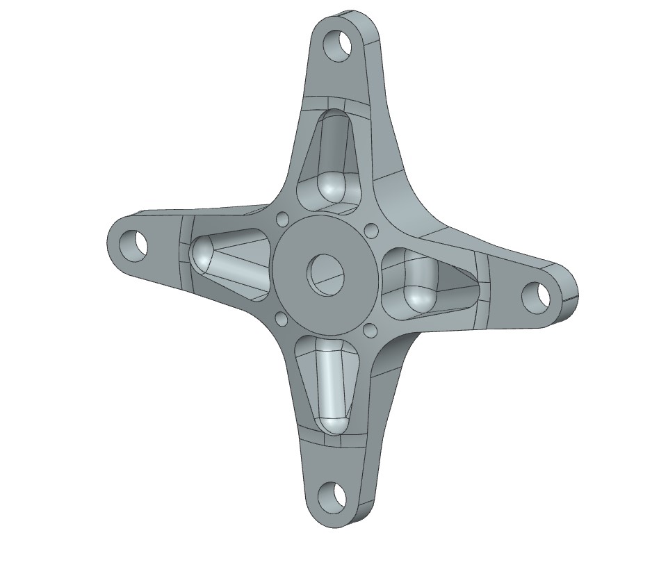
This design is the result of many iterations derived from Finite Element Analysis in Ansys and generative design perfromed in Fusion 360. What made this so difficult was the fact that the trilobe profile (the hole that transfers torque from the spindle to the wheel) changed. As such, force propogation through the whole trilobe was affected, making it very hard to balance weight, machinibility, and strength. After many hours of running FEA, I ultimatley settled on this design, which is slighty weaker than last year but it is lighter and far more machinable.

Analysis
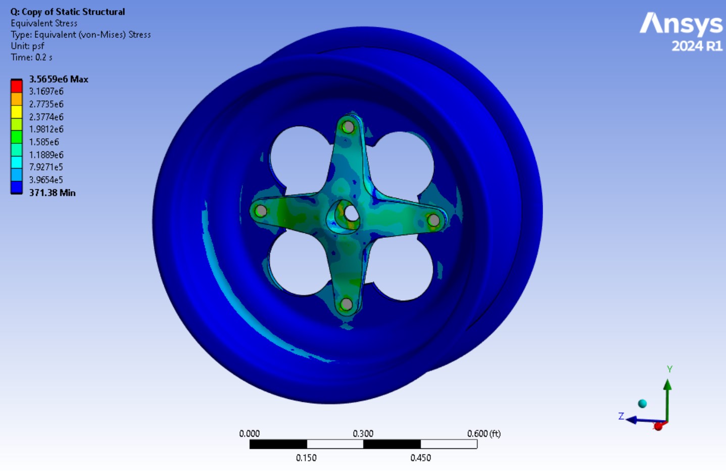
What you are seeing on the right is an assembly level structural analysis simulation in Ansys. The 12 loads for this simulation were taken directly from our wheel force transducer testing, and account for the max forces and moments seen in all coordinate directions. For the boundary conditions, the hub is cylindrically constrained along the trilobe surface (which is where torque is applied from the rear half-shaft), and has a frictionless surface support along the bead of the wheel. From here, I setup the 12 max force/moment loadcases, setting the bead as the load bearing surface. I also setup different coordinate systems corresponding to different wheel rotations to make sure that the hubs could take any expected load in any orientation. These simulations were also used to inform the design of the hub by changing areas that had stress concentrations.

Manufacturing
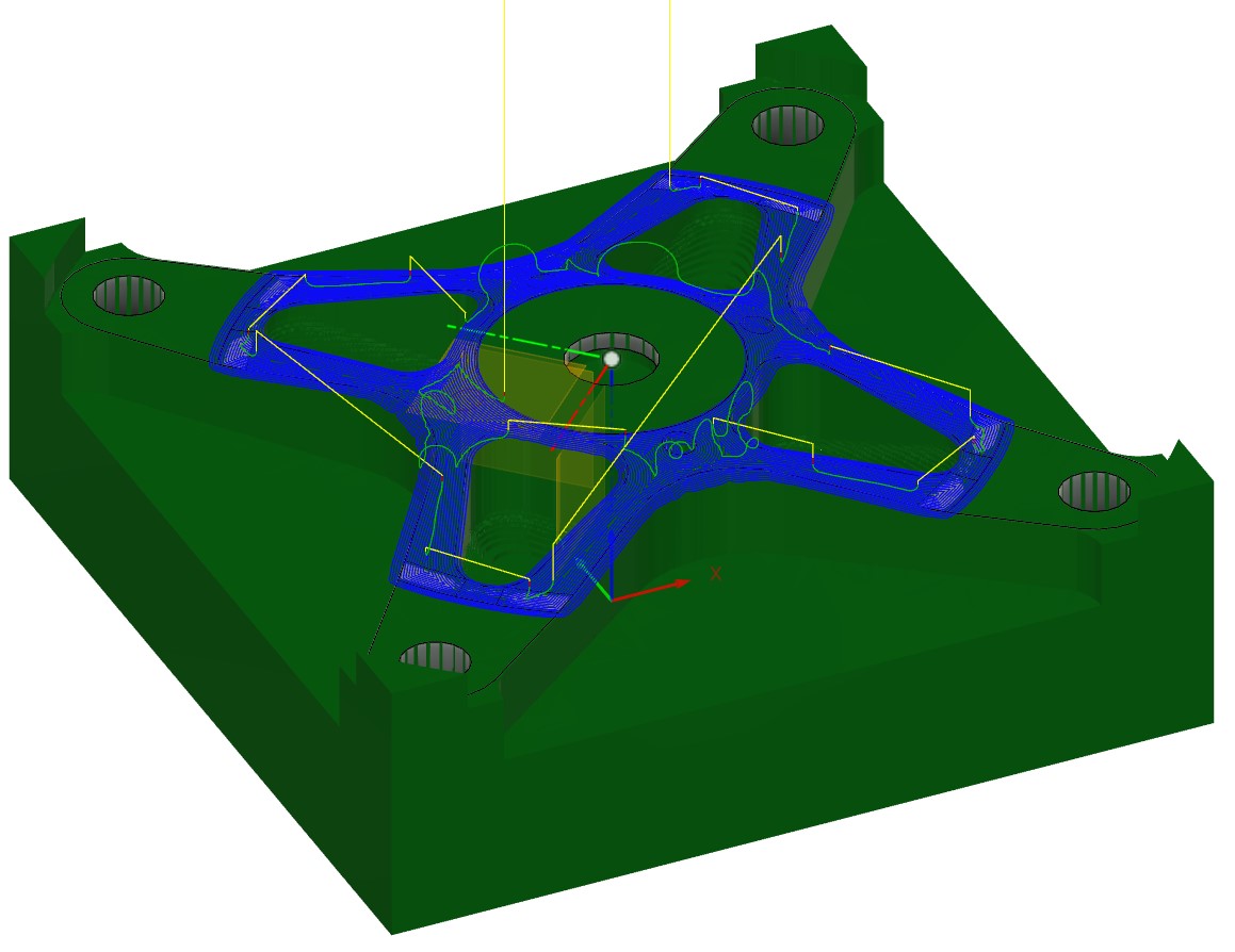
The CAM profile for these hubs was done in Fusion 360. Machining was a two fixture operation on a 3-axis CNC mill. The roughing passes were done with a half inch end mill and finishing passes for contours done with a half inch ball nose. The mounting holes are not nominal sizes so they were interpolated with a quarter inch end mill. In the image, the corners were left to increase stability during the second machining operation.
